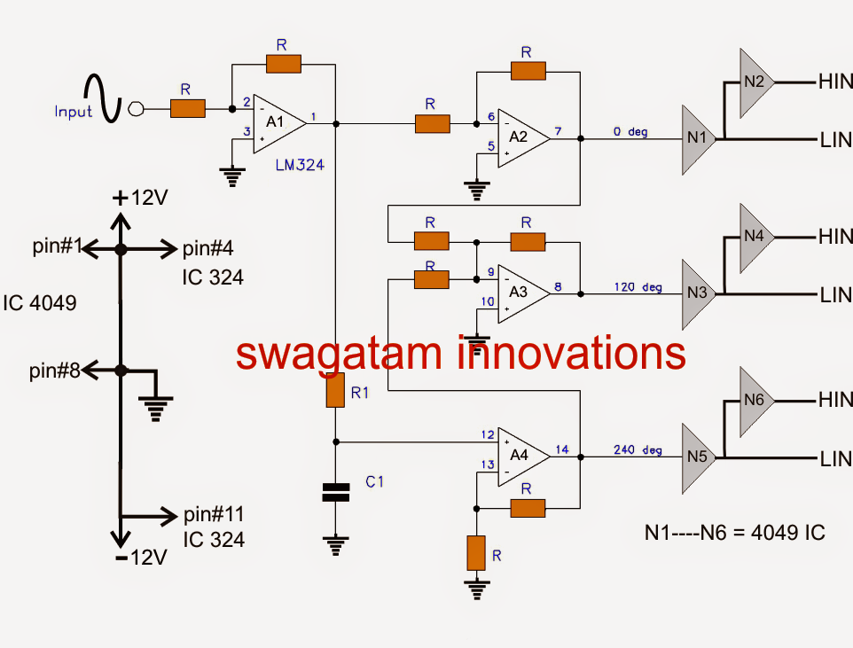
Three-phase pwm inverters with a r-l load. Simplified representation of a three-phase pwm inverter Single phase pwm inverter three phase pwm inverter circuit diagram
Three Phase Inverter Schematic Circuit Diagram - Circuit Diagram
Phase inverter circuit homemade simple circuits make three driver arduino solar bridge ic full using electronics stage projects artikel von Pwm inverter evaluating Inverter pwm schematic wiring basic power prosoundweb
Switch mode inverter circuit diagram
Simple 3 phase inverter circuit – homemade circuit projectsSimplified representation of a three-phase pwm inverter Simple 3 phase inverter circuit – homemade circuit projects3 phase inverter circuit diagram pdf.
Pwm inverter circuitCircuit diagram of three phase inverter1 using svpwm Pwm inverters6 best – simple inverter circuit diagrams – diy electronics projects.
Inverter pwm transistor six switch switches
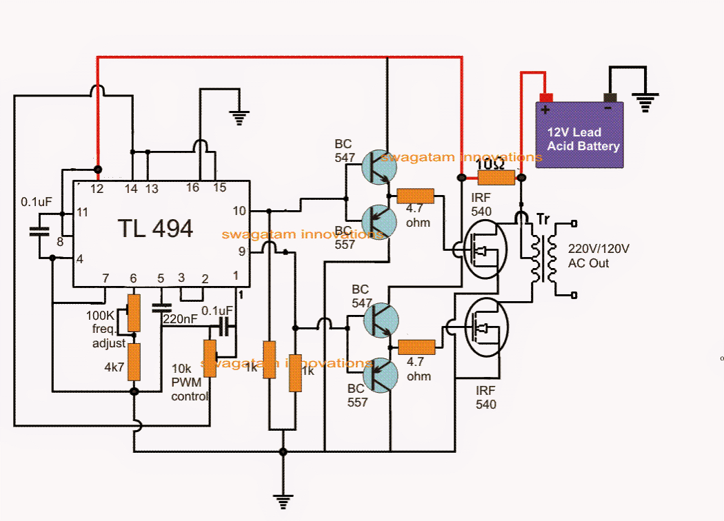
What is a three phase inverter?Ic tl494 pwm modified sine wave inverter circuit Three-phase voltage source pwm inverter the circuit model of a typicalThree-level single phase inverter circuit.
Three – phase pwm inverterInverter mosfet arduino circuits diagrams Inverter pwm watt circuits3 phase pwm inverter circuit diagram.

Inverter phase circuit thyristor diode conduction degree
Pwm inverter circuit sg3524Inverter phase circuit three generator make diagram pwm single solar homemade circuits simple explained wave wiring projects electronic section next Three phase inverter circuitSingle phase pwm inverter circuit diagram.
Evaluating the performance of a single phase pwm inverter using 3525a3 phase pwm inverter circuit Single phase pwm inverter circuit diagram3 phase inverter wiring diagram.

Inverter fig5
Inverter pwm tl494 ic circuit sine wave modified pinout functions executing above looking many pictureHouse wiring inverter circuit diagram Arduino three phase inverter codeMore inverter power?.
Inverter pwm3 phase pwm inverter circuit diagram 1, three phase inverter circuit3 phase pwm inverter circuit diagram.

Three phase inverter schematic circuit diagram
3 phase igbt inverter circuit diagramInverter circuit diagram using sg3524 .
.


